Key takeaways
- Map the changing height, depth and access under a staircase using a station-by-station worksheet before comparing storage furniture.
What's inside
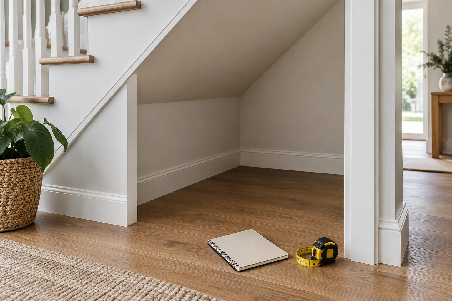
Measure under-stair storage as a series of usable sections, not as one maximum height multiplied by the floor area. The slope can change the fit across a cabinet’s width and depth, and a unit that fits inside the recess may still be impossible to assemble or open there. Create a profile map, then check each candidate against the lowest point it will occupy.
This guide covers an existing accessible recess. It does not establish whether an enclosed stair void can be opened or altered. Leave stair structure, fire-protective enclosure, services and required access unchanged; get the appropriate professional advice before any proposed building work.
Mark the boundaries of usable space
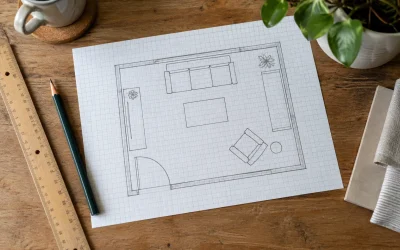
Sketch the recess from the front and from above. Identify a fixed starting point, such as the left wall at floor level, and label it zero. Mark skirting, pipes, vents, sockets, access panels and any sloping or stepped underside. Photograph the empty space from both ends so a measurement can later be connected to the right feature.
Distinguish the overall opening from the space you are willing and permitted to occupy. Equipment access, an adjacent door or an existing circulation route may remove part of the apparent storage area. Do not quietly subtract these restrictions from memory; draw and label them on the plan.
Measure at stations across the opening
Choose stations that capture every change in the slope or obstruction. Record the horizontal distance from zero, height at the front and height at the back of the intended cabinet position. Add intermediate checks wherever a beam, trim piece or uneven surface creates a lower point. There is no useful universal station spacing for every staircase.
Measure depth at the same stations. A recess may narrow toward the back, while skirting can prevent a cabinet from reaching the wall. Record the nearest actual obstruction rather than the theoretical wall line. Keep all dimensions in one unit and note whether the floor has a covering that will remain under the furniture.
Use a profile worksheet
| Station | Distance from zero | Front height | Rear height at planned depth | Usable depth and restrictions |
|---|---|---|---|---|
| A | Low end of proposed unit | Measure here | Measure here | Record skirting and service access |
| B | Middle of proposed unit | Measure here | Measure here | Record any local projection |
| C | High end of proposed unit | Measure here | Measure here | Record doorway or reach limit |
| Extra point | Any change between stations | Check lowest feature | Check lowest feature | Explain why it matters |
Take a second reading of the limiting dimensions. If two readings disagree, resolve the reference point instead of averaging them into an apparently precise number. Keep the original observations so you can distinguish a measurement correction from a changed furniture position.
Compare a rectangular unit with the entire profile
For each proposed unit, draw its complete width and depth on the plan. Find the lowest available height anywhere over that footprint. Compare the product’s assembled dimensions, including feet and top projections, with that restricted envelope. Then add the installation and operating space required by its instructions; a zero-gap geometric fit is not necessarily installable.
Check how the unit reaches its final position. A tall cabinet assembled lying down may require more height to tilt upright than its final standing height. Do not calculate a shortcut and assume assembly is permitted in place; use the exact model’s instructions or ask the supplier about the intended recess.
A worked profile example
Imagine a cabinet position extending from 60 to 120 cm along the opening. In this illustrative survey, the available height at its low end is 82 cm at the front but only 76 cm at the rear. A proposed 80 cm high unit therefore fails the rear check, even though its front appears to clear the slope.
A 72 cm high unit would leave 4 cm at that lowest measured point. That is a preliminary geometric result, not approval: feet, uneven flooring, assembly instructions and door operation still need checking. Moving the unit toward the higher end may help, but it also changes the whole footprint and the access available beside it.
Separate storage fit from door-system fit
IKEA’s SKYTTA planning guide makes two model-specific points relevant to this distinction: its ceiling rail needs a flat surface parallel to the floor, and storage behind the doors must remain reachable and openable. The guide warns about a drawer trapped behind a door overlap. These requirements should not be replaced with a general assumption that any sliding system can follow a stair slope.
If doors or a custom enclosure are part of the proposal, make that a separate installation brief. Record the clear opening in each door position and show how a drawer or removable box travels through it. A photograph of a fitted cupboard does not reveal those movement constraints.
Finish with an access check
Place empty boxes representing the proposed storage locations without obstructing the route. Try reaching the back and removing an item while standing or kneeling where you would normally work. Keep frequently used items where they can be retrieved independently, and avoid turning a deep low corner into a space you cannot inspect or clean.
Save the profile sheet, product dimensions and unresolved installation questions together. Order only when both the furniture envelope and its access requirements are accounted for. The useful output is a measured storage plan, not a claim that every cubic centimetre beneath the stairs can be filled.